by Mike Beigel and Elliott Randall (MIX Magazine 1980)
Over the last decade we have seen innumerable new pieces of sound-altering equipment hit the market, the studio, the stage, …the pocketbook. In the article that follows, we will discuss one of the most important of these tools – the envelope controlled filter. As the technically oriented musician is well aware, increasing your musical/sound options is both necessary and great fun.
Envelope controlled filters have been used by musicians since 1972. We are accustomed to thinking of them – and using them as ‘automatic wah-wah pedals,’ but this usage has been dictated by the forms of products available rather than the musical possibilities inherent in the Envelope Controlled Filter as a signal processing system. In the same way that a simple bandpass filter can be turned into a complex – and very versatile parametric equalizer, so the system elements of an Envelope Controlled Filter can be expanded in form and function to provide a very sophisticated musical effects processor.
Musicians and recording engineers are constantly searching for sounds that are not just new, but useful in expanding their musical expression and palette of sound colors. Basic inventions in the field of sound modification, as in any other technological area, are infrequent; but technological improvements of existing devices and systems are much more accessible. As we gain more insight into the nature of musical sound processes, we are able to develop systems which allow more effective use of the basic building blocks of sound processing. Thus we can breathe new life into systems that were previously quite limited, and produce genuinely new sounds that are qualitatively superior and different from those we now work with.
 Fig 1. Envelope Follower with input and output waveforms
THE PARAMETRIC ENVELOPE FOLLOWER
An envelope follower provides a control voltage signal in response to the instantaneous ‘loudness’ of an audio signal input. You can compare it to a standard VU meter, which indicates the ‘average’ volume of an audio signal in a visual display. The envelope follower’s internal electronics actually resemble a VU meter circuit in many ways. Figure 1 shows a simple system diagram of an envelope follower, along with the audio input waveforms and output control signals associated with it.
Comparing the input AC signal and the output DC Control signal, we see that the output signal closely conforms to the ‘shape’ of the input signal, but without the complexity of all the audio frequency components.
 Fig 2. Parametric envelope follower
A simple envelope follower, like the one just shown, provides a signal which very closely ‘tracks’ the average instantaneous amplitude of the input. This corresponds very closely to the rhythmic and loudness properties of the input, and therefore any audio modification process controlled by a simple envelope would also display this characteristic. In fact, most available envelope-controlled filters are limited by the fact that the envelope follower ‘tracks’ the input so closely. Hence, the characteristic ‘automatic wah’ sound so typical of envelope controlled filters.
We can augment the design of the envelope follower by giving it independent ‘attack’ and ‘decay’ times. The idea is almost identical to the ‘attack’ and ‘decay’ controls on an envelope generator found in synthesizers, but with an important difference: The attack (onset) and decay controls of the parametric envelope follower function in relation to the input signal. When the envelope output voltage is less than the input signal, the ‘attack’ mode approaches the input signal with a time-constant set by the ‘attack’ pot. When the envelope output voltage is greater than the input signal, it decays toward the input signal level with a time-constant set by the ‘decay’ pot.
 Fig 3. Envelope shapes
One of the most versatile filters for processing musical signals is the ‘state-variable’ or multi-mode filter. This type of filter allows lowpass, bandpass and highpass characteristics (Figure 4). Each has its distinct sound character and musical uses. Most musicians are familiar only with lowpass filter characteristics common on synthesizers, and often miss the interesting musical effects obtainable with the two other modes.
 Fig 4A. Filter modes
The amount of resonance (or ‘Q’ or ‘peak’) of the filter is vitally important to the perceived sound quality. With little or no ‘peak’, the sound quality is subtly modified, only in terms of ‘brightness’ or clarity. With very high ‘peak’, the sound quality is grossly modified, becoming vowel-like when swept, or even accentuating individual overtones of the musical signal.
 Fig 4B. Filter ‘Q’ peak
Both the cutoff frequency and the ‘peak’ of the filter’s response can be voltage-controlled (and thus envelope controlled). That, of course, is what transforms the filter from a simple ‘equalizing’ device into a musical effect.
DRIVE AND CONTROL FUNCTIONS
The versatility of a musical effect system depends on how the components interact with each other. If we have an envelope follower producing a control voltage, and a voltage controlled filter responding to that control voltage, we still have many choices over how the control voltage affects the filter response. The envelope voltage sweeps the filter but in which direction, over what range, with what accuracy? We might want the filter cutoff frequency to move hardly at all, or down instead of up, or over its full range. Perhaps we want to vary the filter’s ‘Q’ or ‘peak’ proportional to the envelope signal instead of simply setting it with a knob.
 Fig 5. Filter control system
The filter control system is the interface between the envelope follower and the voltage controlled filter, and it’s as important as either of them. In one version, ‘start’ and ‘stop’ controls determine the trajectory of the filter. The filter cutoff frequency varies from the ‘start’ position (with ‘zero’ envelope) to the ‘stop’ position (with ‘full’ envelope). The settings of these two controls thus determine the sweep width, direction, and starting point with complete flexibility.
EFFECTS LOOP
The Effects Loop in an Envelope Controlled Filter system serves a function similar to the hole in a doughnut. It’s really not there, but it enhances the product dramatically. The Effects Loop consists of two jacks, strategically located after the audio input, out of the way of the envelope follower, and before the voltage-controlled filter.
The real reason the effects loop is there is that many additional audio processes which make the musical signal more interesting (especially if we want to filter it) badly degrade the signal’s natural envelope. Fuzz tones, ‘soft distortion’ devices and compressors are some examples. The filter likes them, but the envelope follower hates them. So we provide a place where they can process the signal before it’s filtered, without bothering the envelope follower. Echo and chorus machines, octave dividers or doublers, and many other effects find surprisingly advantageous uses in the ‘effects loop’ position.
 Fig 6. Effects loop
More aspects of product design could be covered, but these constitute the major recent advances in envelope-controlled filter technology (apart from specific product designs.)
STUDIO USE AND SETUP
At many recording sessions in which the Envelope Controlled Filter was used, I realized that the studio setup and use of this device is critical. The way the system is set up in the context of the studio can ‘make or break’ the utility of the effect. The following guide-lines will help you use the effect to its fullest advantage in the studio:
- The effect is best used live rather than post-mixed. This is because envelope-controlled filtering is an interactive effect, rather than just an automatic sound process. The musician plays through the effect as an integral part of his/her performance.
- The musician using the effect should be able to hear it on his/her own head phones or monitor speaker.
- The effects loop of the Envelope Controlled Filter should be accessible to many different sound processes: those brought along by the musician as well as those available in the studio.
- The effect and the direct signal from the musician’s ‘unprocessed’ instrument should be available on separate faders. A proper mix of processed and unprocessed material often provides the optimum musical sound.
- The control panel of the device should be available ‘hands on’, either to the musician and the device.
- Signal levels to the device should be optimized to provide the best signal-to-noise ratio, while preventing overload distortion. Remember: at high values of the ‘peak’ control, the device can easily exhibit a gain of 30 dB at its resonant frequency.
 Fig 7. Studio Setup for Envelope Controlled Filter
Figure 7 shows a preferred studio setup for the Envelope Controlled Filter. Using this or a similar setup (and plenty of creativity) you will be able to use this effect along with the rest of your electronic arsenal to produce many beautiful and ‘unheard-of’ new musical sounds.
NB The Mu-Tron III was arguably the very finest envelope filter ever available on the market, embraced by myriad musicians including Stevie Wonder, Bootsy Collins, yours truly, and a host of other creative sound-meisters. In recent years, a rogue version has appeared – and that one is nowhere near as good as Mr. Beigel’s original. (Don’t waste your money on the imitation.) Now the good news: A newer, better version of the original Mu-Tron III, redesigned by Beigel has emerged. I absolutely love this – and I can guarantee that it will make you smile – broadly! It’s called the Tru-Tron 3X, and I strongly suggest you click here to find out more.
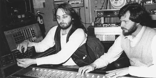 Elliott Randall and Mike Beigel, Media Sound Studios, N.Y. 1979
 1980
1980